


How to Design Parts for CNC Machining
2026-04-17
Designing a part that looks good is easy. Designing a part that machines well is a skill.
CNC machining is subtractive manufacturing – you start with a solid block of material and use rotating cutting tools to remove everything that isn’t the final part. Understanding the physical limits of cutting tools and the behavior of materials is the key to designing parts that are functional, fast to produce, and low in cost.
|
Table of Contents: |
|
3. Leave Room for Workholding |
|
4. Optimize Hole Design |
|
5. Design Threads Wisely |
|
6. Reduce Unnecessary Tight Tolerances |
|
7. Avoid Features That Need Special Cutters |
|
8. Consider Multi‑Axis Machining |
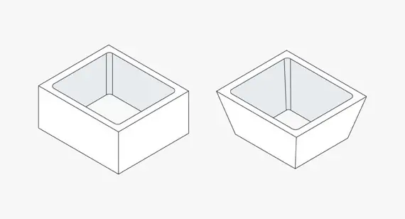
1. Consider Tool Accessibility
The tool has to “reach in” to cut. If your part has a deep, narrow slot, the tool may not reach the bottom, or it will vibrate excessively due to long overhang.
Rule of thumb:Keep the ratio of cavity depth to minimum opening width ≤ 4:1. For example, if a slot is 10 mm wide, try to keep its depth below 40 mm. If you must go deeper, consider a stepped design or machining from both sides.
2. Avoid Thin Walls
Thin walls are one of the biggest challenges in CNC machining. When a cutter engages a thin wall, the metal pushes away like a spring and then springs back, causing chatter, out‑of‑tolerance dimensions, and even scrapped parts.
Rule of thumb:For metal parts, try to keep wall thickness no less than 0.8 mm for aluminum, or 1.5 mm for steel and titanium. For plastics, go even thicker. If you must have thin walls, consider adding ribs or changing the process (e.g., wire EDM).
3. Leave Room for Workholding
The part must be held securely during machining. If the part has a complex shape, is all curved surfaces, or is very small, workholding becomes difficult and time‑consuming.
Rule of thumb:Add machining tabs or fixturing flats to your design – extra material that is later removed. Alternatively, design at least two parallel surfaces or a clampable region. Never assume that a magnetic or vacuum chuck will solve every problem.
4. Optimize Hole Design
Drilling is one of the most common and efficient operations in CNC machining – but only if you follow the rules.
Rule of thumb:
Prefer standard drill sizes (e.g., Ø3.0, Ø4.0, Ø5.0, Ø6.0, Ø8.0, Ø10.0 mm).
Through holes are easier to machine and clear chips better than blind holes.
For blind holes, try to keep depth ≤ 6× diameter. Deeper holes require special tools (gundrills).
Where possible, have the hole entrance and exit on flat surfaces. Drilling on curved surfaces is tricky (requires spotting drills or 5‑axis positioning).
5. Design Threads Wisely
Threading (tapping) is a step where things often go wrong, especially with small sizes or hard materials.
Rule of thumb:
Use standard coarse threads (e.g., M4, M5, M6, M8) whenever possible. Avoid fine pitch or non‑standard threads.
Thread depth does not need to exceed 1.5× diameter (e.g., for M6, 9 mm deep is plenty). Deeper threads add little strength but greatly increase tapping difficulty and the risk of tap breakage.
Avoid threads smaller than M2. If absolutely necessary, consider threaded inserts or a design change.
6. Reduce Unnecessary Tight Tolerances
The tighter the tolerance, the longer the machining time and the higher the cost. A CNC machine can run fast at ±0.1 mm, but at ±0.01 mm it must creep along and be inspected repeatedly.
Rule of thumb: Apply tight tolerances only where assembly fit truly requires them – bearing bores, dowel pin holes, mating surfaces. For overall profiles, lightening pockets, chamfers, and non‑mating surfaces, use general tolerances (e.g., ±0.1 mm or ±0.2 mm).
7. Avoid Features That Need Special Cutters
Special‑shaped tools (T‑slot cutters, dovetail cutters, form cutters) are expensive, slow, and prone to breakage.
Rule of thumb: If possible, design undercuts or T‑slots so they can be machined from the side or as separate pieces. If you truly need them, make sure the width and depth are within standard tool ranges and clearly call them out on the drawing.
8. Consider Multi‑Axis Machining
3‑axis machining often requires multiple setups (machine the top, flip to machine the bottom, then stand it up for the sides). Each setup adds positioning error and time.
Rule of thumb: If the budget allows, design with 3+2 axis or full 5‑axis machining in mind. This means avoiding undercuts where possible, so that most or all of the part can be machined in one setup.
- Aerospace CNC Machining: How to Balance Strict Precision and Processing Speed
- Precision Machining for EV & Advanced Robotics: Meeting Next-Gen Industry Demands

Get an online quote and injection molding design analysis today.